Skymaster ARF PLUS 1/8 F-16 Instructions
Manual


We
wish you had a nice flight.
ARF
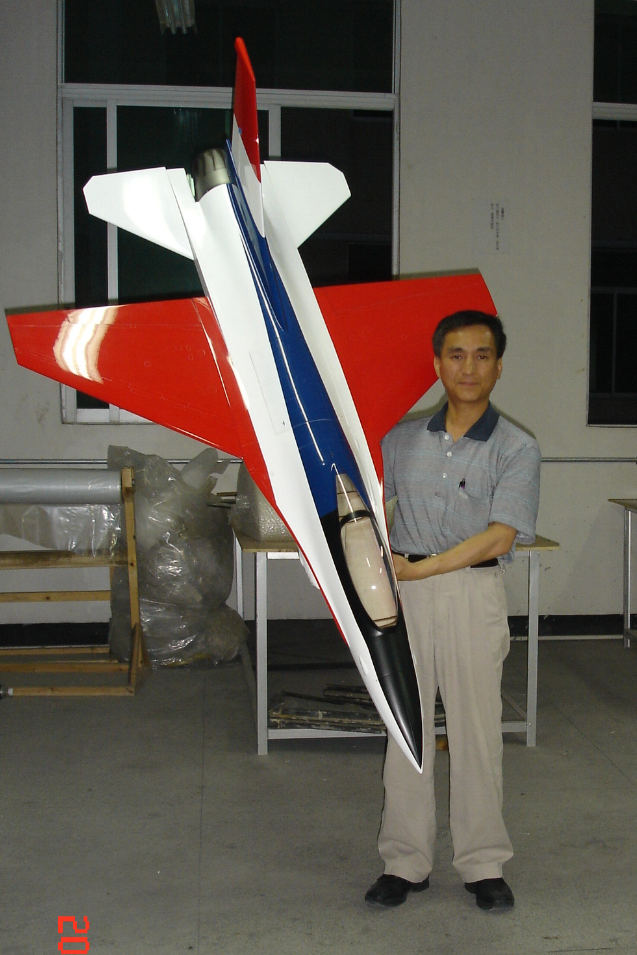
PLUS F-16 Designer & Test Flight Pilot : Anton Lin
Sincerely
your
Skymaster
RC Jet Models
http://www.skymasterjet.com/
F-16
Outline
Chapter
1....................... Introduction
Chapter
2....................... Parts count
Chapter
3....................... Rudder
Chapter
4....................... Fuselage
Chapter
5....................... Engine
Chapter
6....................... Wing
Chapter
7....................... Radio setup
Chapter
8....................... Balance and
final assembly
Chapter
9....................... Flying
Appendix.......................
Gear doors
Introduction
Skymaster
presents the 1/8 scale F-16 Viper. We hope you enjoy this scale rendition of one
of the world’s most popular modern jet fighter bombers. With over 4000 F-16
being produced to date, there are thousands of color schemes to choose from, and
many excellent books and references available from plastic model vendors, and on
the Internet.
The
Skymaster F-16 is a fully molded composite model utilizing some of the latest
techniques to create a very lightweight and highly prefabricated almost ready to
fly jet. You will enjoy the “live Kevlar hinging” with precision gap sealing
on the flaperons that saves time and is also very aerodynamically clean.
You
should read this entire manual before starting to build the aircraft so that you
can familiarize yourself with any parts and tools that you will need to complete
the airplane.
This
model jet is not a toy and takes attention to detail during building, and
experience flying radio control airplanes to safely fly it. If you do not have
learned the skills necessary to build the aircraft please seek help.
To
be able to be successful in flying the F-16 you should be able to at least fly a
fast (100 mph) radio controlled airplane with complete confidence. In any case
you should get the help of an experienced Jet modeler if possible.
Chapter
2
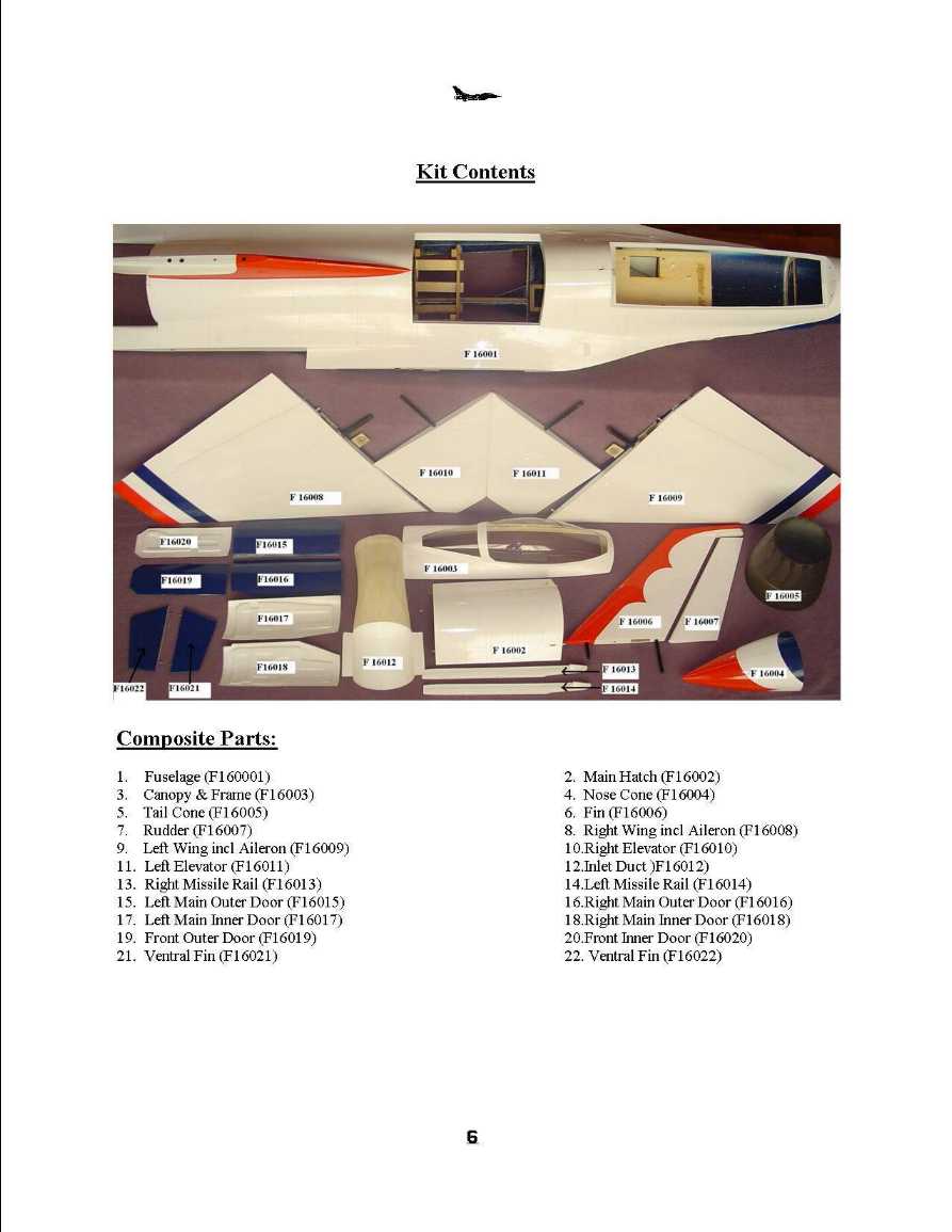
Parts
Carefully
unpack your kit and inspect it for damage. Please notify your dealer immediately
if you find shipping damage. If you can take digital photos of the damage it
would be helpful for Skymaster and your dealer. Make sure that before you throw
away any packing you confirm you have all your parts, as some are small and can
get lost in the packing material.
You
F-16 kit should contain
Fuselage.......................
1
Nose
cone....................... 1
Top
Hatch....................... 1
Tail
cone....................... 1
Ventral
fins....................... 2
Left
wing....................... 1
Right
wing....................... 1
Wing
carbon spar....................... 2
Left
stab....................... 1
Right
stab....................... 1
Vertical
stab and rudder....................... 1
Front
vertical stab carbon spar.......................
1
Rear
vertical stab carbon spar.......................
1
Left
main gear door....................... 1
Right
main gear door....................... 1
Nose
gear door....................... 1
Wood
accessory pack....................... 1
Hardware
accessory pack....................... 1
Chapter
2
Parts
you will need to complete this chapter
1
X vertical stabilizer and rudder assembly 1 X Rear vertical stabilizer spar 1 X
Front vertical stab spar. 1 X 10-32 x ¾” rudder hold down bolt. 4 X
servo screws 1 X JR 3421 servo or equivalent, masking tape, 5 min epoxy, control
horn, control rod with clevises.
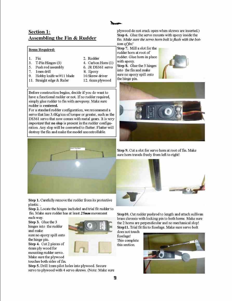
- The
servo blocks are mounted in reverse of normal so that you can remove the
servo later. It is important that the servo blocks are centered on the servo
and the mounting blocks stick out equally on both sides of the servo. Screw
servo to mounts as shown, using servo screws and servo mounting blocks.
Using a file or Dremel tool cut a relief grove for the servo-mounting tab.
- The
reason we mount the blocks to the servo first is so that when we glue in the
servo mounts into the vertical stab base it doesn’t deform the skin of the
vertical stab. Make sure that the servo with the mounts attached slides into
the vertical stab without deforming the skin. If it does distort the skin of
the stab, sand the block down until it no longer deforms the skin of the
stab.
- Using
5-minute epoxy glue in the servo mounts take care not to get too much epoxy
on the servo. You can put some car wax or grease on the servo sides before
gluing in the mounts this will make it easier if you get some glue on the
servo by accident. Let the servo mount set. For the first few min check
alignment of the servo to make sure it dose not slip. Alternatively if your
in a rush we have used Gel CA glue in place of epoxy, but you must be very
careful to not to get it on the servo and your placement of glue must be
accurate.
- Put
a few strips of masking tape on the stab approximately where the servo sits.
Now measure the foreword and rear bottoms of the servo and transfer the
measurements to the tape, and draw a line that represents the bottom of the
servo. Remove the servo and place it on the alignment marks so that it is in
the same position as it was mounted in the vertical stab. Now mark where the
servo arm hits the skin and the center of the servo shaft. Using a Dremel
tool cut a small slot over the center of the slot cut out marking. Make sure
that you aligned the servo as you will have it mounted in the fin, and you
are cutting the slot on the right side of the rudder. Mount the servo back
in the vertical stab and cut the rest of the slot carefully making sure your
alignment is correct.
- Check
alignment of the rudder and its hinges. You might have to enlarge the hinge
holes to get the rudder to move freely. The proper alignment of the hinge
pivot points is shown below. Dry fit until satisfied then glue in with 5 min
epoxy or 30 min epoxy, before gluing the hinges in, lightly coat the pivots
with thick grease and work them back and forth for a few seconds to work the
grease around, take care not to get any on the shaft of the hinge that glues
into the vertical stab. Now if you get some epoxy into the hinge line it
wont stick!
- After
cutting the slot in step 4 make sure that the servo turns freely and the arm
clears the slot for the full commanded movement of the servo. Center the
servo using your radio system or servo-centering device. Take a ruler and
mark where the slot for the rudder horn is to be mounted. Take care to make
a line that is parallel to the plane of rotation of the servo arm. This will
of course make the horn not parallel to the airflow but due to the mechanics
of the hinge line the best alignment for the servo linkage and horn, is
perpendicular to the axis of the hinge line. The effect of the rudder horn
not being aligned with the airflow is minimal and wont affect the flight of
the aircraft a noticeable amount. Using a Dremel tool or a hobby saw
carefully cut a slot big enough for the rudder horn. Take care not to cut
thru to the other side of the rudder. Rough up the horn gluing area using a
sander, file or Dremel tool. Use masking tape on either side, and front and
back of the slot so that glue does not get on the fin leave about 1/32”
clearance to the slot so you can form a fillet with the glue on the side of
the slot. Using Hysol, Epoxy, or Gel CA glue in the horn make sure you get
glue in the slot and that the horn bottom is touching the skin of the other
side of the rudder. Before the glue dry’s make a fillet then remove the
tape carefully on the skin of the rudder. If you are using slow drying glue
you should use a piece of masking tape to hold the alignment of the horn.
- After
the horn is dried make sure that it attached solidly to the rudder. Pick out
the appropriate sized linkage for the rudder and make sure that it is solid
and has little play. If you have excessive play on the horns you can bush
them using a 3/32 brass tube from K&S. First cut a small length of brass
tube just slightly larger than the thickness of the horn. Drill out the horn
hole using a 3/32” drill. Place the bushing into the horn with one side
sticking out more than the other very carefully drop some thin ca above the
brass tube and let it wick in around the bushing. After using ca accelerator
on the bushing use a file to bring the bushing flush with the surface of the
horn.
- Insert
front and rear spars into the vertical stab then fit into fuselage, use
10/32 X ¾” bolt to
attach the stab from the inside of the rear of the fuselage. Make sure the
rudder wire is not pinched between the rudder and the fuselage as you
tighten the screw. You should use locking compound on the screw to prevent
it from loosening in flight.
Chapter
3 Fuselage
Parts
you will need to complete this chapter
1
X fuselage assembly 2 X Rear horizontal stabilizers 2 X wing spars 2 X flaperon
servo mounts 4 X servo screws 2 X JR 8611a servos or equivalent, 2 X Robart 560
90 degree main retract units, 1 X Robart 560 110 degree nose gear 5 min epoxy,
control horn, control rod with clevises.
- Center
elevator servos using your radio or a servo-centering device, install metal
arms on servos while they are on and centered.
- Mount
both elevator servos with the arms pointing to the top of the fuselage. Use
4/40 cap head screws with washers to mount servos. Do not use the supplied
servo rubber grommets and brass bushings to mount the servos. R/C turbojet
aircraft have little vibration, and high speed flutter is a larger concern
than vibration fatigue.
- Test
fit the elevator horns for fit on the stab pivot rod. Also test the fit of
the stab pivot rod in the aircraft.
- Place
one small nylon washer on each stab pivot rod.
Insert the stab into the fuselage and place another nylon washer on
the inside of the fuselage over the stab pivot.
Fit the stab horn to the stab rod.
Adjust the stab and the horn so that there is no slack between the
stab and horn. Check for free
you rotation of the stab. Evenly
tighten both screws on stab horn and repeat on the other side.
- Using
your radio or servo centering device center both elevator servos.
Next take the control Rod and clevises and adjust them so that the
trailing edge of the elevators are 1/16" above the rear parts of the
fuselage.
- Once
you are satisfied with the alignment of your elevators, tighten your jam
nuts and install safety clips on clevises.
- Using
tie wraps and mounts route your servo wires towards the front radio
compartment. Make sure the
servo wires will not touch the tailpipe or engine in the back of the
aircraft.
Main
Gear:
- Take
your main gear units and test fit them the main gear mounts in the bottom
hatch of the aircraft. Check for clearance on the sides and make sure that
the gear set level in the mounts.
- Assemble
your of wheel and brake assembly by taking the tire and wheel and inserting
the brass bushings into the wheel and brake assembly.
Next take the Axel and insert it into the wheel through the brake and
into the strut make sure that everything fits together correctly.
You may notice some resistance while turning the wheel some brake
drag is normal.
- Insert
your struts into the main gear retracts loosely tighten them we will use
this to align and adjust the main gear mounting.
Manually retract the landing gear to the half up position. The
scissors link should face forward
- Place
the main gear unit strut assembly into the aircraft and the main gear mount.
While holding the main gear in the mounts swing the gear in and out of the
aircraft checking for clearance. Once
you're satisfied with the proper clearance mark one of the holes with a pen.
- Using
a three 32nd inch bit drill both marked holes.
Using a 632 socket head screws attach both main gear assemblies to
the fuselage using the single drilled holes. Finally adjust the main gear
assemblies to fit and clear all bulkheads and fuselage parts.
Drill all remaining holes for the main gear mounts and install screws
and tighten.
- Attach
airlines to the up air nipple and the down air nipple.
You should use the same color on all gear up air circuits, and the
same color on all down air circuits. Make
sure that the airlines are long enough to reach the area behind and below
the engine compartment where you will be installing the air T fitting. After
attaching both up and down air circuits to the T fitting run a single up
line and a single down line to the cockpit area.
Nose
Gear
- Take
your nose gear units and test fit them the nose gear mounts in the bottom
hatch of the aircraft. Check for clearance on the sides and make sure that
the gear set level in the mounts.
- Assemble
your of wheel assembly by taking the tire and wheel and inserting the brass
bushings into the wheel assembly. Next
take the Axel and insert it into the wheel through the brake and into the
strut make sure that everything fits together correctly.
- Insert
your struts into the nose gear retract loosely tighten them we will use this
to align and adjust the nose gear mounting.
Manually retract the landing gear to the half up position. The fork
side of the nose strut should face to the left if you are looking at the
nose of the airplane. The scissors link should face forward.
- Place
the nose gear unit strut assembly into the aircraft and the main gear mount.
While holding the main gear in the mounts swing the gear in and out of the
aircraft checking for clearance. Once
you're satisfied with the proper clearance mark one of the holes with a pen.
- Using
a three 32nd inch bit drill both marked holes.
Using a 632 socket head screws attach the nose gear assembly to the
fuselage using the single drilled holes. Finally adjust the nose gear
assembly to fit and clear all bulkheads and fuselage parts.
Drill all remaining holes for the main gear mounts and install screws
and tighten.
- Attach
airlines to the up air nipple and the down air nipple.
You should use the same color on all gear up air circuits, and the
same color on all down air circuits. Make
sure that the airlines are long enough to reach the cockpit area.
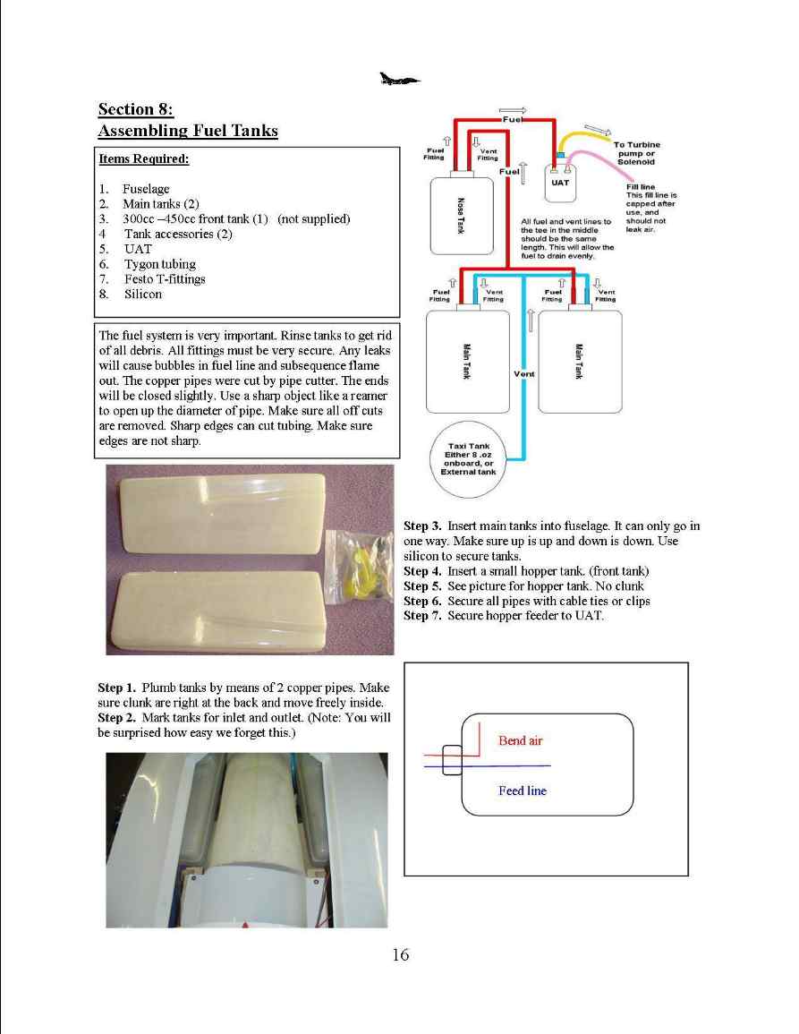
Fuel
system.
- Assembly
of the two main tanks.
- First
take the parts out of the fuel tank bag and see if you have all the parts.
Two main tanks, Two 5/32” copper tubes, length of fuel tube, klunk, rubber
stopper, front and rear stopper plates, and one machine screw.
-
- Assemble
the tank by first fitting the tubes into the rubber stopper as shown.
- Fit
the front and rear stopper plates, and thread the machine screw through the
front plate into the rear plate for a loose fit.
- Fit
the stopper into the hole drilled into the tank. It should be a close fit,
it is too tight use a step drill and just make the hole big enough for the
stopper to fit into, be very careful the fit needs to be tight to seal
correctly. Do not tighten yet.
- Fit
the fuel line and the klunk. Adjust the length of the fuel line so that the
klunk just touches the bottom of the tank as shown. Safety wire the fuel
line by wrapping the wire around the tube once then twisting the wire to
tighten it. Caution the ends of the safety wire is very sharp, all
cuttings should be carefully caught and disposed of.
- Bend
the vent tube as shown. Make sure it reaches the top of the tank.
- Place
the stopper into the tank and tighten. Make sure the tank stopper is tight
and pressure test the tank for leaks using 3 to 5 psi and holding the tank
under water to check for bubbles.
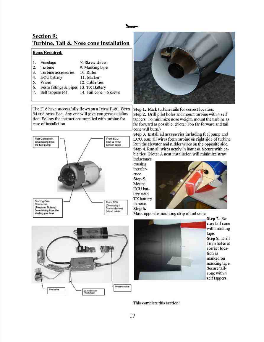
Turbine
Installation for middle mounted turbine.
You will need 1 of your turbines standard engine mount, tailpipe and, 4 X 6-32
hex head wood screws.
- Start
by removing the aircraft tailcone if it is mounted, then slide the tailpipe
in from the rear of the aircraft. The mounting tabs should be able to rest
on the tailpipe mounting rails. Do not screw in the tailpipe at this time.
- First
remove the top hatch. Fit the your turbines mount on the engine rails. You
may need to trim a little wood off of the rails to get the mount to fit
correctly.
- After
the turbine in its mount will set level on the engine rails move the
turbine, and the tailpipe back and forth to adjust the end of the large
outer exhaust to be 15 mm from the bell mouth of the tailpipe. Check the
alignment of the turbine by looking up the end of both tail pipes to see if
your turbine is centered in the front of the tailpipe. Once satisfied with
the alignment, drill a 3/32 ” hole through the engine mount mounting
holes. Screw in one 6-32 Hex wood screw then check for alignment. Do this
for the remaining screws.
- Follow
your Turbines manufacturer recommendations for installing your
accessory’s. Here are some sample locations for the accessories for
different turbine installations.
Home


