
Skymaster ARF F-5 Instructions Manual (update 22 Feb 2005)
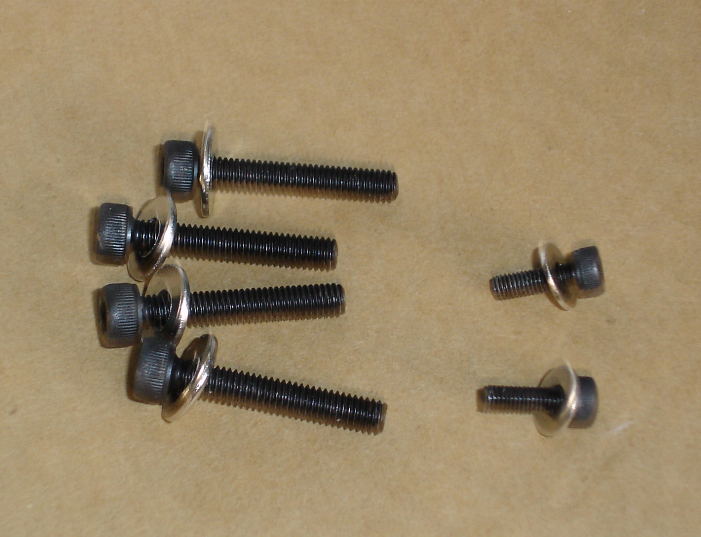
You will need a container for small parts, a 3 mm hex wrench, a 2.5 mm hex wrench, Phillips screwdriver. First remove the 6 screws from the front of the back fuselage take care not to misplace these screws, as there are no extras in the kit. There are 4 X 4 mm screws and 2 X 3 mm screws.
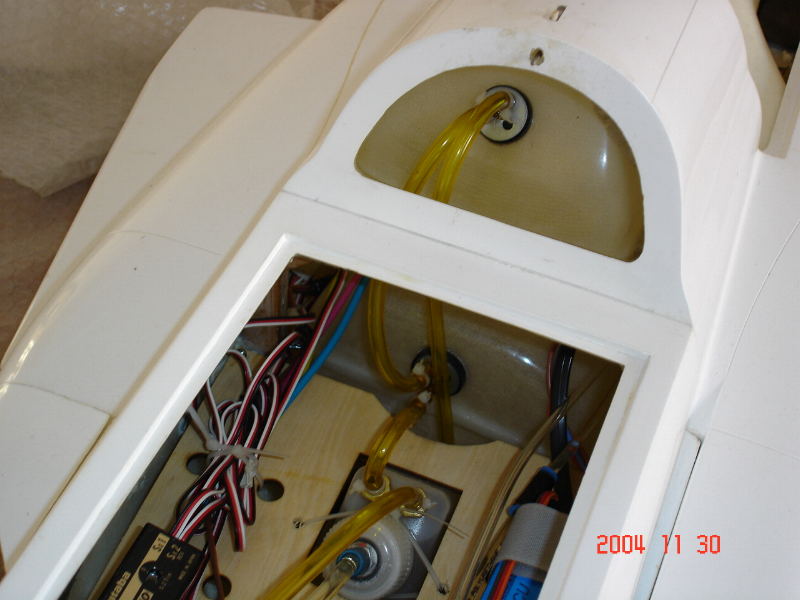
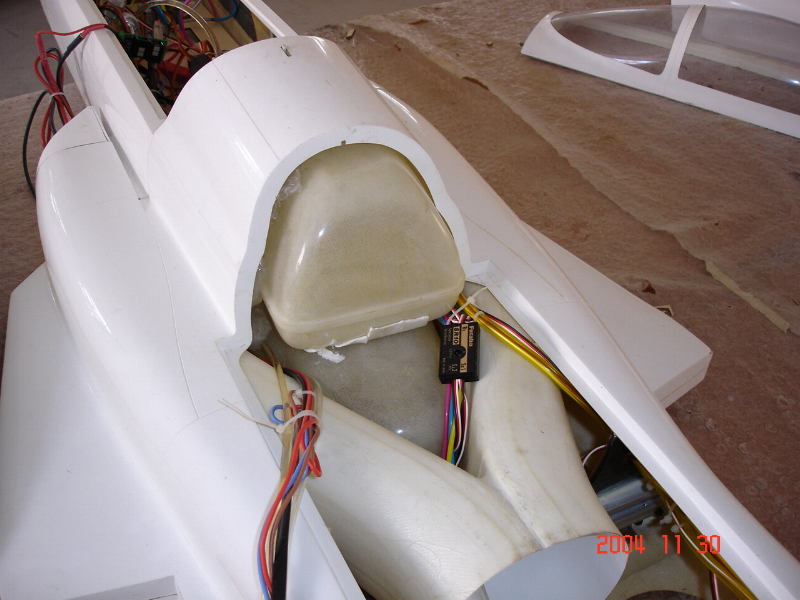
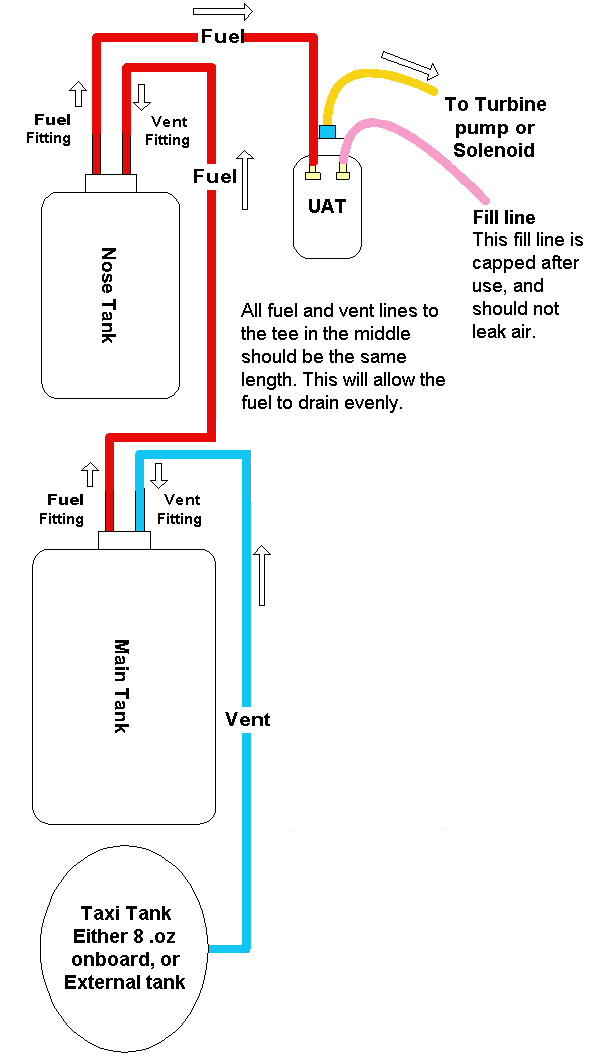
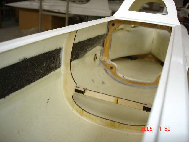
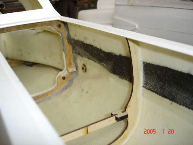
Remove the servo tray from the nose section. Install the front fuel tank in the front of the fuselage before attaching the nose section. The fuel and vent lines should be attached at this time.
Carefully fit the nose section to the rear fuselage by
slipping it in from the top down. Fuselage.
It is not critical that you follow the exact pattern,
you just need to insure that even pressure is used to tighten the screws,
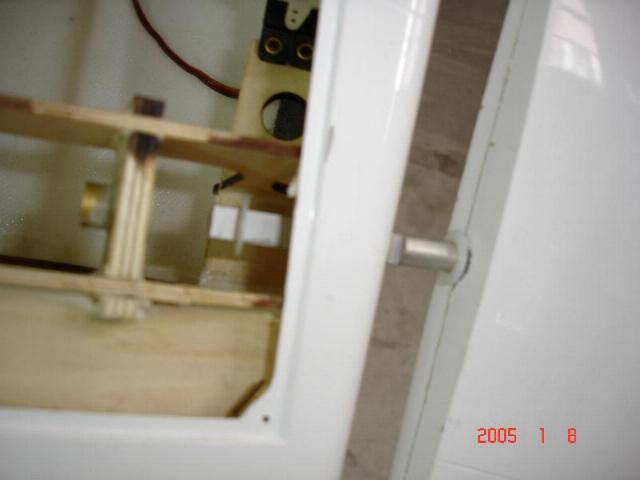
Take out the 4 screws and Bottom Cover and install the Rudder Fin
Attaching
the Rudder to the fuselage.
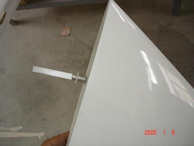
Unscrew
the 5-40 attachment bolts from the bottom of the stabilizers.
Plug
in the stabilizers to the fuselage. The left and a right side are different, you
can tell which is which by the servo access doors that should face inside.
setup
the two screws for the rudder fin
When you place the rudder fin in the fuselage, please make sure you use thread
lock or a spring washer to set the screw in tightly.
Also, make sure you check the screw regularly to ensure that the rudder
does not come loose. Please keep in
mind, if the rudder is even slightly loose, it could cause flutter and serious
damage on the plane.
Remove
the top hatch. Turn the fuselage upside
down
and lay it on a padded stand or box so that you can easily access the rear
Elevator access panels.
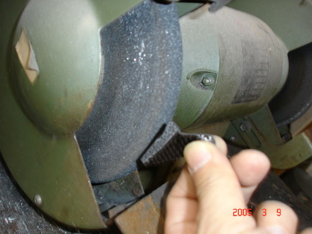
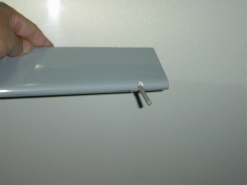
Take one of the Elevator and remove the control horn that is on the Elevator shaft. There should be a plastic washer on the shaft of the Elevator one thick place them in a safe place. Do the same for the other Elevator.
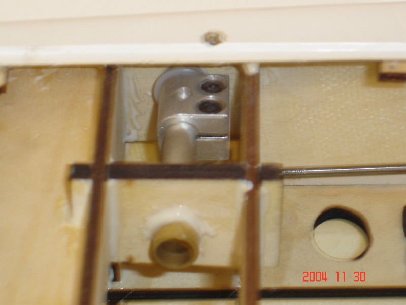
connect the push-pull rods for elevator servos control
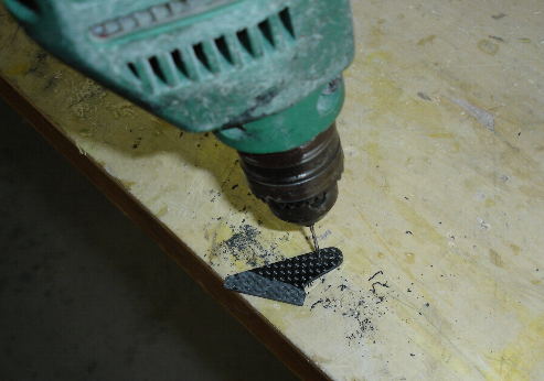
Take the control horns and carefully thread in a 4-40 set screw make sure not to force it in, just screw it in a turn or two, it will be tightened later. Take an Elevator and place a thin washer on the Elevator shaft. Slide the Elevator shaft into the Elevator bushing on the side of the fuselage push it in all the way and make sure it rotates freely.
Slide the Elevator out till the shaft just protrudes into the fuselage interior. Using your hemostats or long nose pliers put the thick washer on the shaft first then the control horn with the horn against the outside the edge of the fuselage.
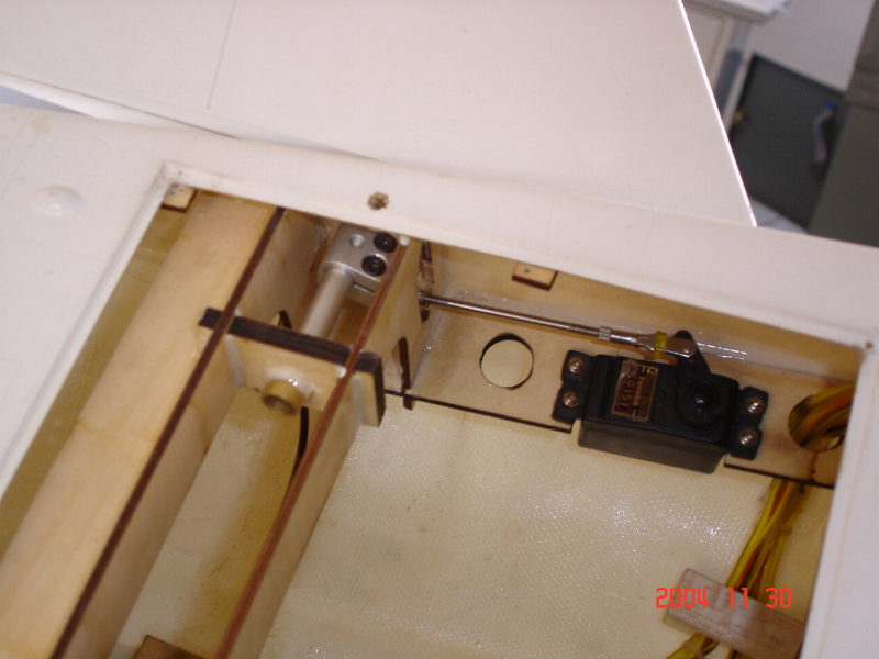
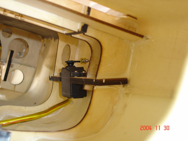
install the servos for the Elevator
A
little trick is to put a small spot of grease on the washer to make it stick to
the control horn first then slide it on. Push the horn all the way on to
the
Elevator
shaft then tighten the 5-40 screws in the control horn so that it just starts to
grab onto the
Elevator
shaft. Use
your direct servo control cable from your transmitter to your radio system to
center the
Elevator servo.
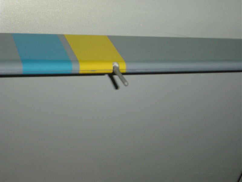
Take
the trailing edge of the Elevator
and line it up with the points of the ends of the fuselage.
First
tighten one screw then the other; you must go back and forth between the 2
screws till both are tight.
After
you are satisfied that the horn is tight disconnect the control rod and turn the
Elevator
so that you expose the 4-40 set screw.
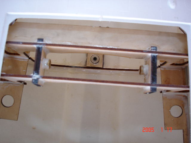
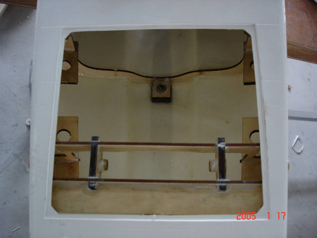
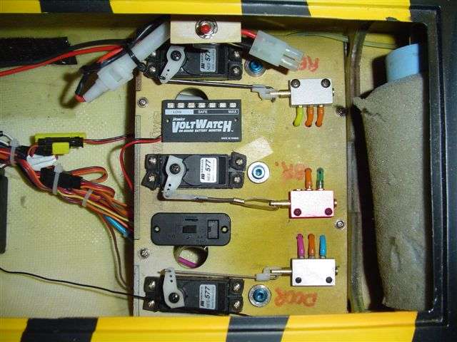
install main gear with setup air pipes for air breaks for the main gear
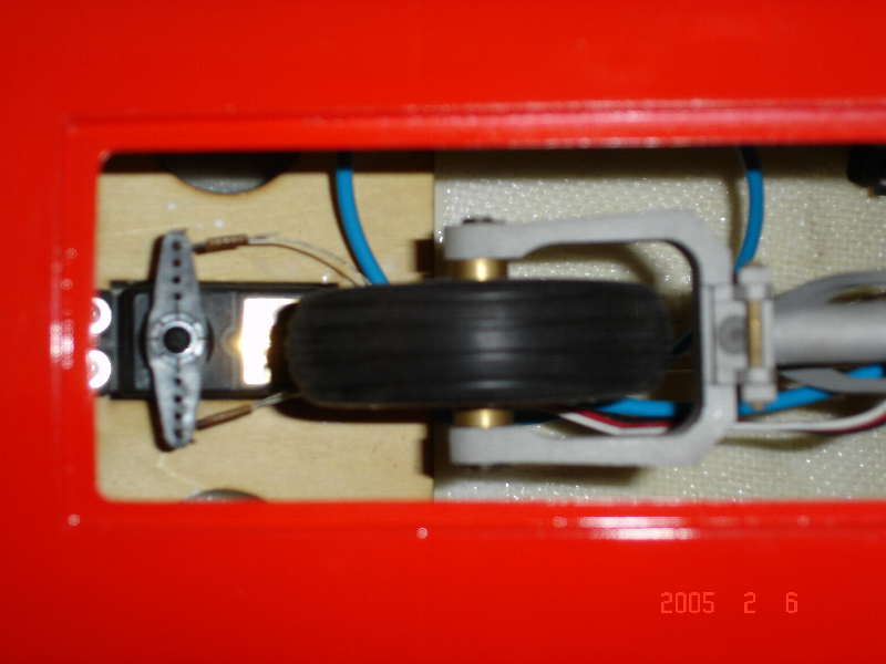
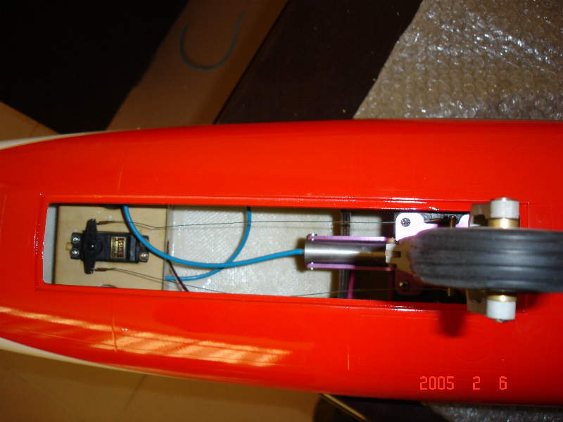
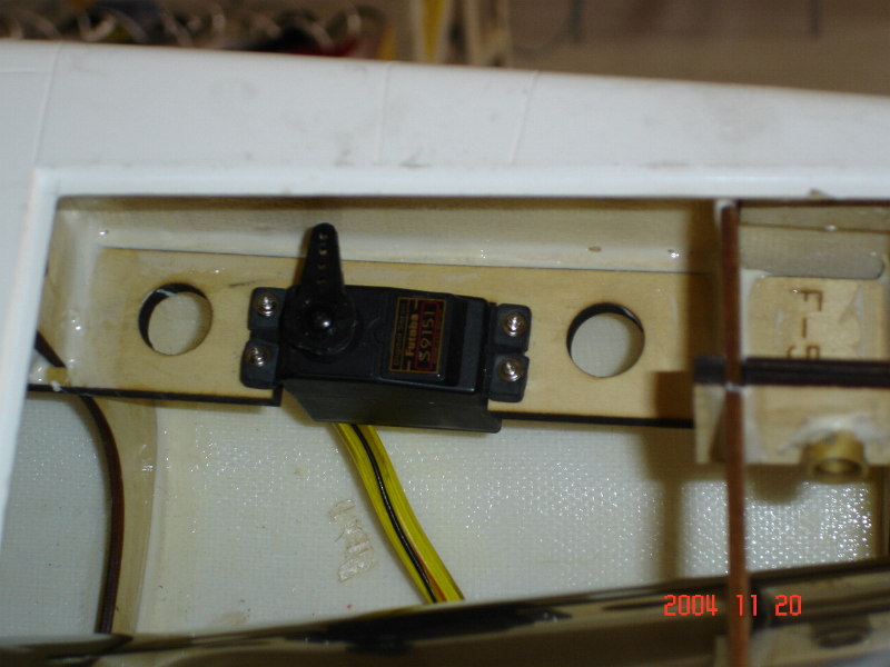
setup the front servo and make two piano wires control to the nose gear
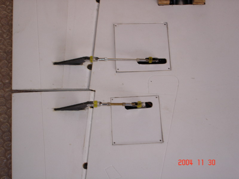
Glue the 6 Hinges for Ailerons with Flaps
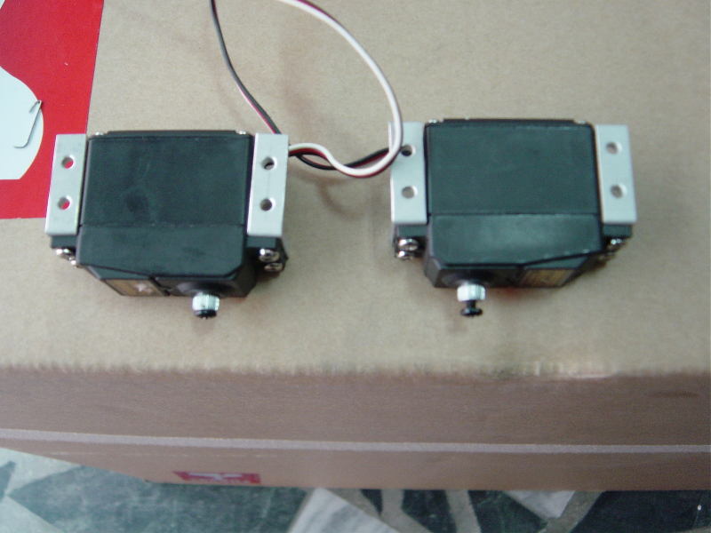
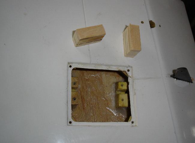
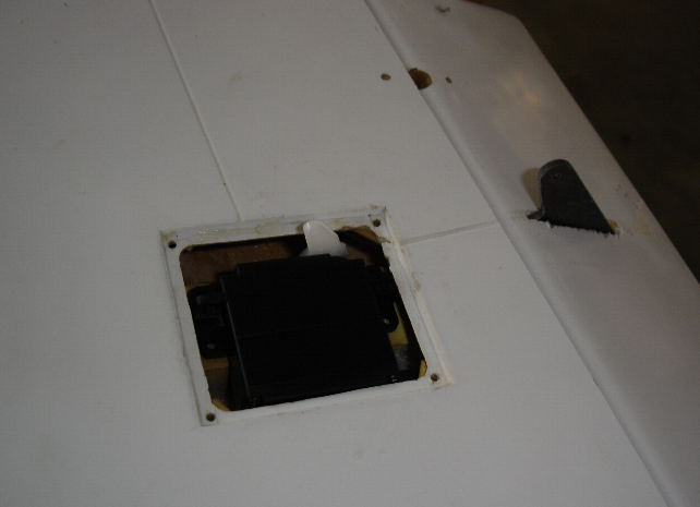
install the two servos for the Flaps
We suggest use of the Futaba # 9204. (#9151) or JR # 8425 (#8511 or 8611) servos for Both Flaps
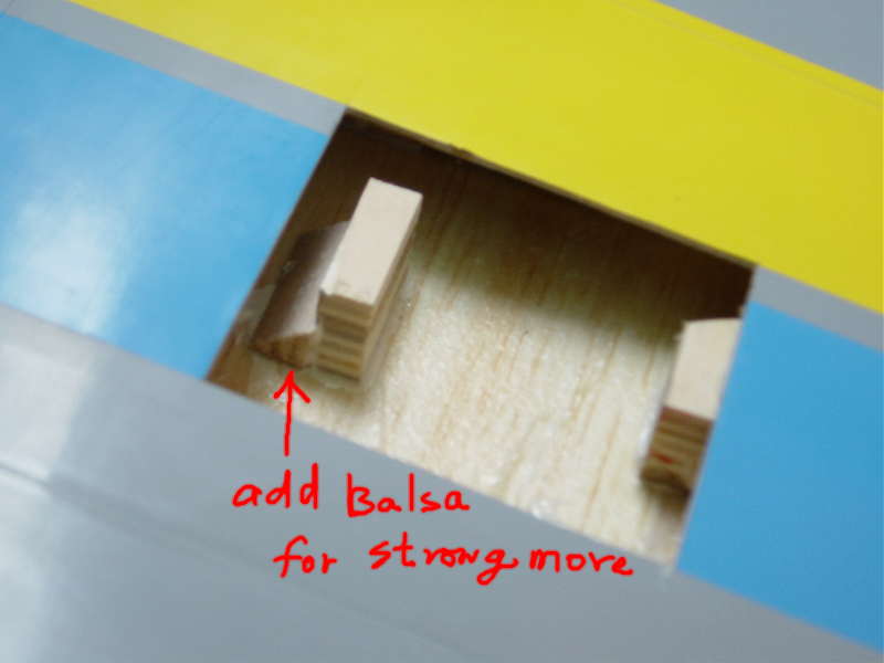
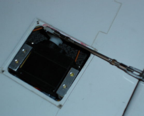
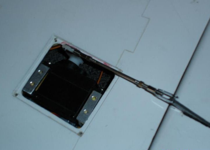
all Servo mounts must add glued Balsa for Strong more
Note:
Please make sure the servo is secured to the mount.
The servo mount base should have enough surface area to hold it.
If you only glue the servo mount directly to the wing surface
without additional support may cause the whole thing to rip off in extreme
conditions. This will cause serious
damage to your plane such as fluttering.
We suggest you use a thin plywood or layer of fiberglass to
increase the base surface space before you glue the servo mount..
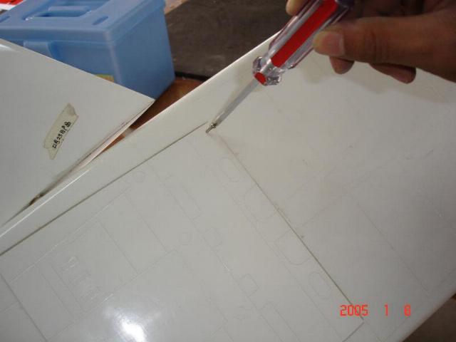
Glue the servos mounts for the Aileron servos and cut the hole then glue for Control Horns

install the aileron
servos, connect
both push-pull rods for Aileron servos control
We
suggest use of the JR # 3301servos for the ailerons
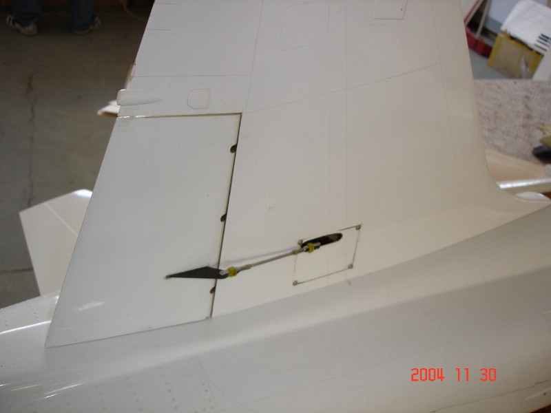
install the Rudder
servo, connect
both push-pull rods for Rudder servo control
We
suggest use of the JR # 3301servo for the Rudder
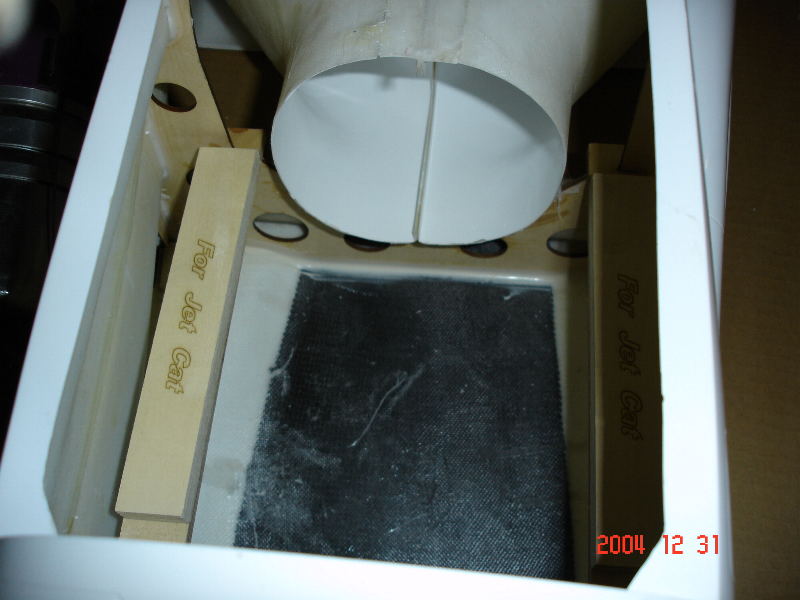
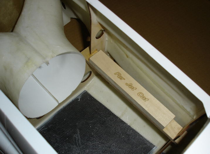
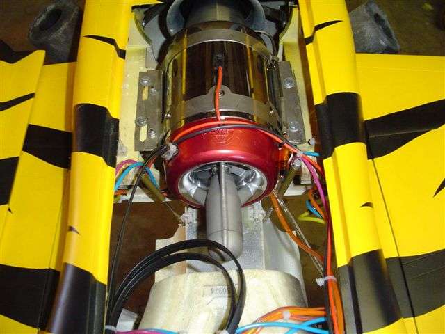
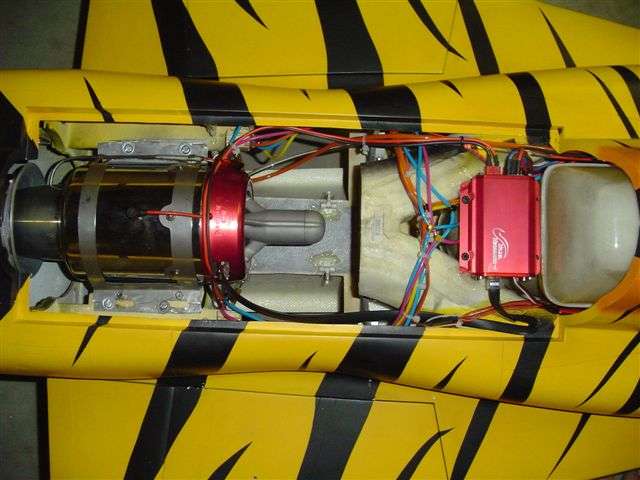
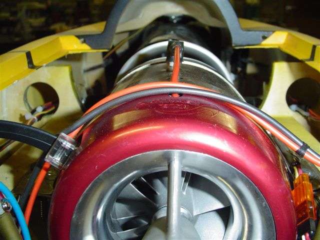
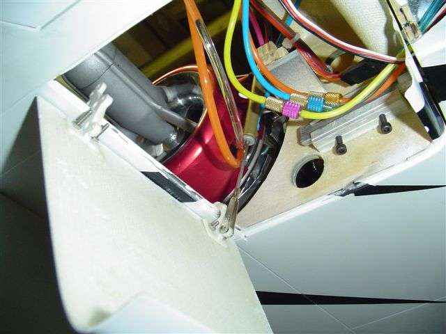
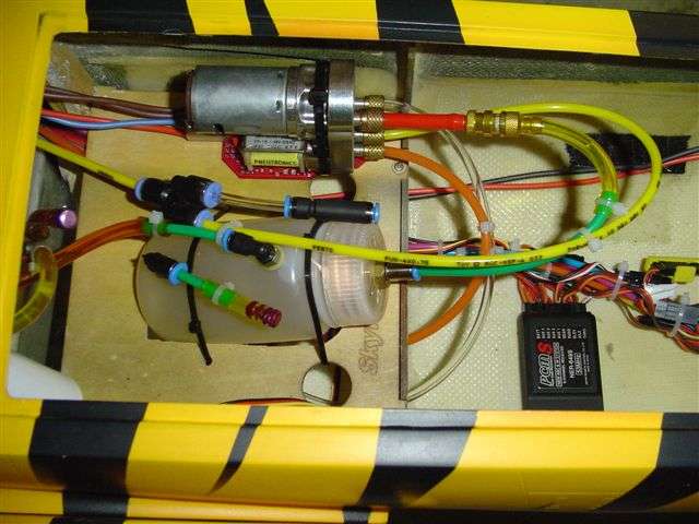
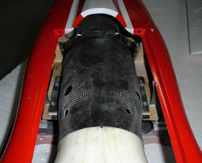
If you use the Jet Cat Engine you must add glued two (2) engine wood mounts
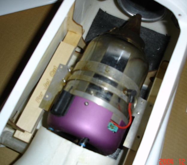
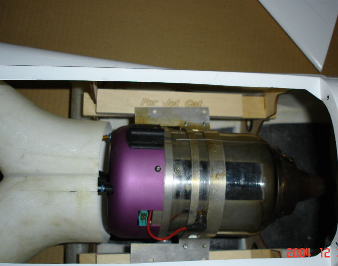
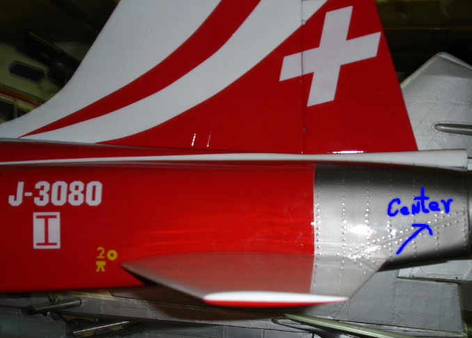
make sure the engine is on the center line and adjust the engine position fore and aft as necessary
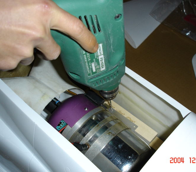
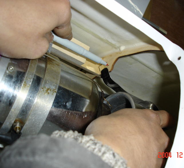
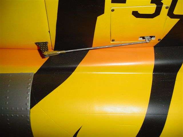
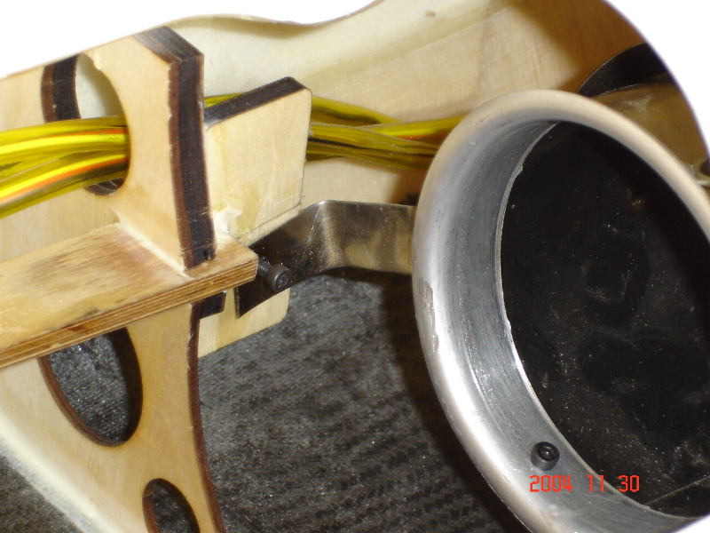
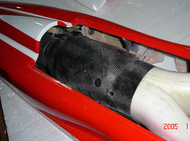
The tail flange has two brackets. Mark and drill holes in the brackets so they line-up with the holes in the right / left bulkheads holes.
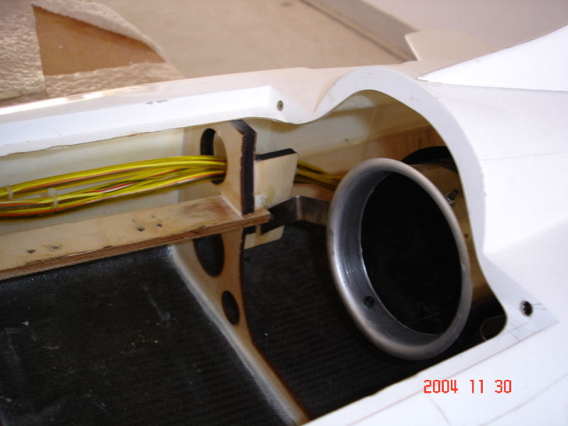
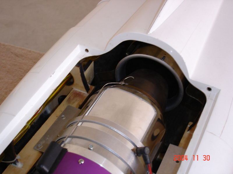
make the holes to fasten the dual wall tail pipe
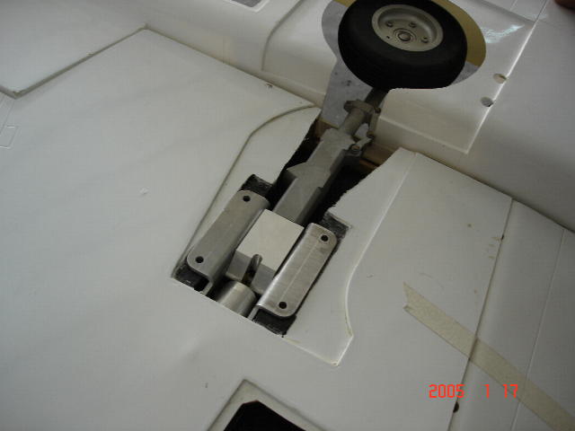
install main gear with setup air pipes for air breaks for the main gear
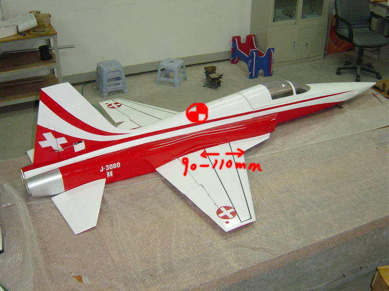
the C/G 110mm measured from the leading edge, The most forward point of the wing (without Fuel and Gear Down)
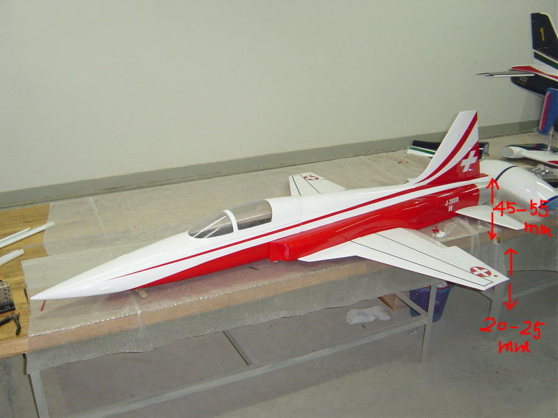
set-up elevator function for up / down movement for each to between 45 mm ~ 55 mm
set-up ailerons function for up / down movement for each to between 20 mm ~ 25 mm
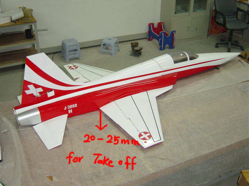
set-up Flaps function for down movement 20mm for Talk off
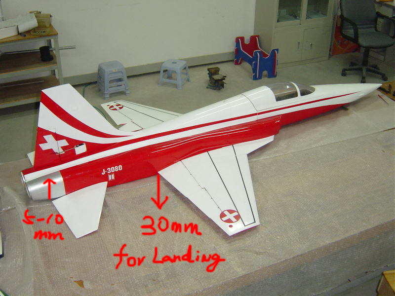
set-up Flaps function for down movement 30 mm and approx 5-10 mm of up elevator with down flap for Landing
the Rudder travel 30-40mm both ways (45-50 mm for good knife edge)